New possibilities: we check the Onshape configurator
Currently we are working on better use of Onshape tools / functions.
This program is constantly developed - new features are released again and again, which proves that we chose well. This year we got (among others) possibility of creating configurable parts. This has inspired us to create easy customizable/ modifiable? projects of simple devices or sub-assemblies. Such a solution could greatly accelerate our work and in the effect reduce the production costs of the device.
But let us think for a moment ... has anyone else done this before us?
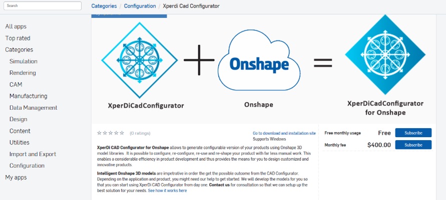
Our first step was to check Onshape App Store. There is only one app: Xpedri Cad Configurator”. It’s founders write, it allows you to quickly create different versions of devices after preparing the base model in Onshape. This program gives us great features, which can significantly reduce the time needed for preparing 3d documentation. But at the same time it generates another fixed cost for us - which is independent of the number of our serial devices orders. We would also have to install the program on a specific computer. This is a big limitation for people who work remotely and value mobility. Moreover, the possibility of creating this configuration applies to model only - in program description there is no information about 2D documentation, which is needed in manufacturing process of our devices.
Let’s think about whether we can do it ourselves - and thus reduce the cost of documentation. Or maybe we can also create “configurable” 2D documentation?
Onshape configurations
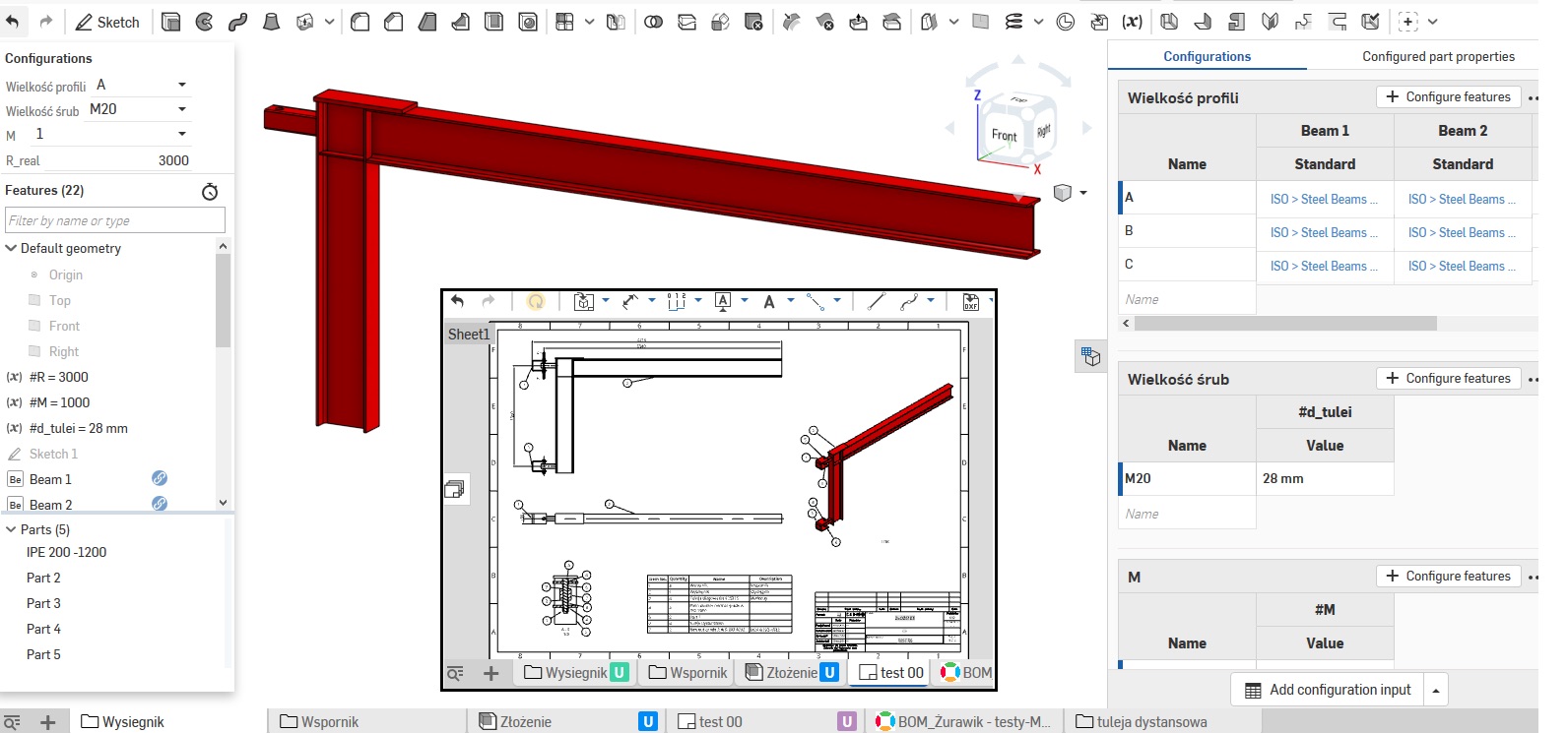
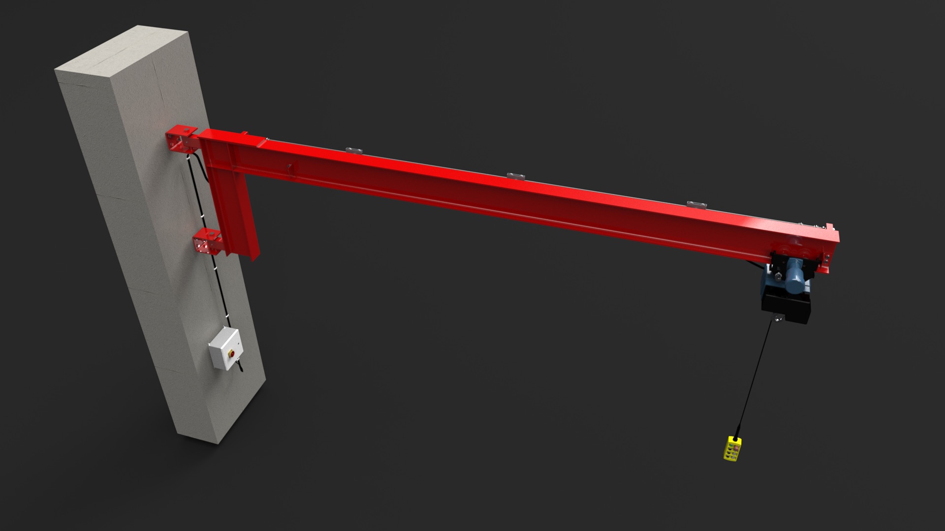
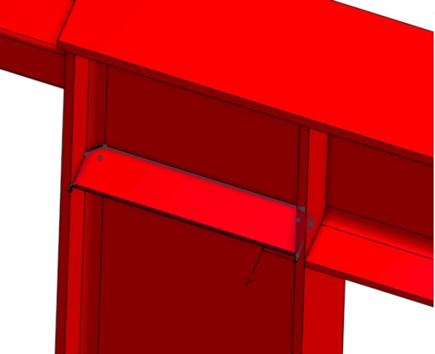
We have started our attempts based on model of simple wall mounted jib crane.
Modeling
Our test model consists of following parts:
- jib
- wall bracket
- distance sleeve
- plain bearing
- screw with washer and nut
To simplify calculations of our series jib cranes we decided to pick most of parameters from previously prepared list of options.
Serie of jib cranes means serie of calculations. To save some work we decided that most of varying parameters will be picked from list and only one of them (outreach) is allowed to be written, according to client’s wish.
What and how can we change there?
jib:
- size of beams and screws, spacing of wall brackets are chosen from list of options
- outreach is written
Plate connecting jib parts and ribs should adjust to size of beams without our participation.
bracket:
- type of bracket and size of screws are chosen from list of options
assembly:
- to changed main elements we have to adjust size of standard parts
So far, with a small amount of work, we can create models of jib cranes with different parameters.
2D documentation
What about drawings?
- assembly drawings, drawings of single parts - we click “update” - and after a while we get new drawing. Sometimes we have to adjust scale of drawing, move some views or balloons with items numbers, and that’s it.
- drawings of welded parts - in our documentation welded parts are shown on the same drawing as welded assembly. According to our experience as well as our manufacturer's preferences it is more comfortable and faster to work with such drawings, than create separate for each part. To update views of detailed parts on welded structure drawing we have to pick for each part in which configuration it should be shown. Later on we make some necessary visual changes, the same as on assembly drawing. Updating such a drawing is more time consuming than assembly drawing. It is also quite easy to make mistake. Despite these inconveniences we can produce 2D documentation faster than usual - creating new drawings from scratches.
The documentation creating process of the next crane can be seen on the video:
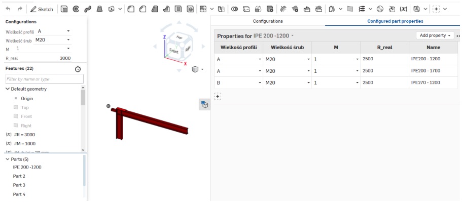
BOM and parts names
Proper part naming is time consuming and arduous task - we would like to minimize it. Here, however, we encountered some problems.
- Onshape configurations enable manually typing parts names for each configuration. We’re glad that Onshape team gave us this possibility. But we have to tell the truth - solution is not satisfying and consumes too much time.
- Some of the parts can be named using feature scripts. These elements have the same main part of the name, and differ only in dimensions. So we can write prefix once for all configurations and feature script takes care of the rest - that’s what we like!
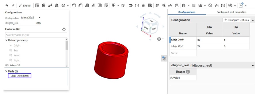
- Our first attempt cooled down our enthusiasm a little bit. We use mm as units, but in the name we have meters everywhere. For small items it’s really poor solution due to long names.
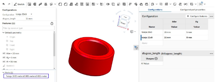
We found a solution, however. Few changes in model and from “Tuleja 0,02meterx0,005meterx0,015meter” we managed to get much nicer “Tuleja 22x5x15”. Here is what we did:
- For “list” type configurations - instead variables “length” type we have created “number” type ones, and typed unit next to dimensions on sketches.
- For “configuration variable” we have set “real” type instead of “length”. Unit, as previously, is being typed next to dimensions in sketches.
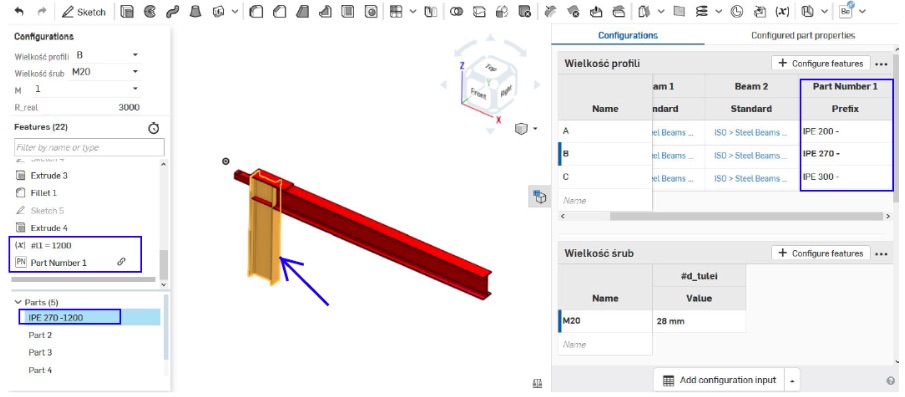
- Another group of items require varying prefix for different configuration. To name some of them we can create new variables and configure part of the name such as size of beam profile. It requires more effort to get proper name. Is it possible to derive profile name to part name?
- And what about items, which can’t be named using variables because their’s dimensions depend from other items?
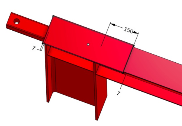
- And maybe it is possible to derive control dimensions to part name?

Summary
After the first tests we are very satisfied with configuration in Onshape. Despite some inconveniences we have seen that configurations will save us plenty of time while creating documentation of similar devices. And all of that without further investments in tools. We have noticed some issues, it is possible we will create our own feature scripts to solve them, just as we did with
beams
and
pins
. If you have any ideas to improve our solutions don’t hesitate to contact us. We are happy to share our knowledge and we believe that together we can discover a new level of design.