Return to the cranes
Return to the design of offshore cranes
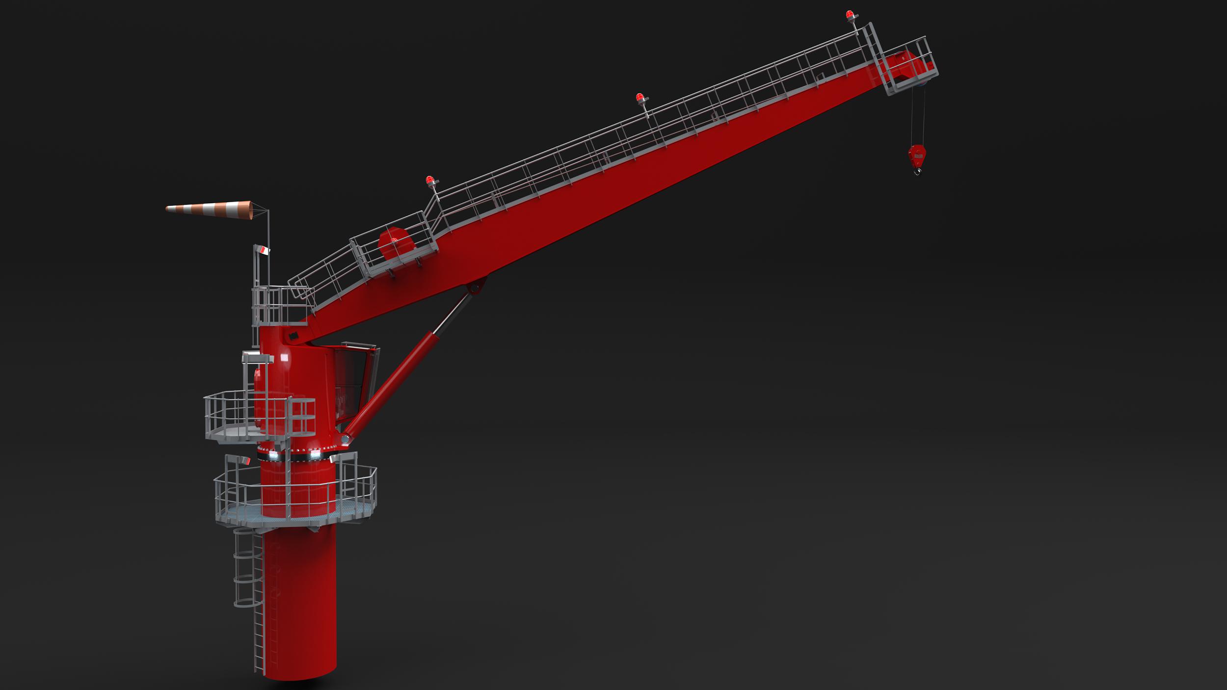
Recently, we have been talking with customers about the design of cranes - mainly RAM luffing and knuckle boom, designed for various vessels. Due to the large variety of crane types and their technical parameters, we decided to improve the design of this type of equipment in order to reduce the amount of time spent on the project and to be able to propose to the client the parameters that are necessary to achieve his goals.
Using our experience in this field and new engineering tools, such as FEM calculation programs and a fully parametric CAD system, we decided to improve our methods and use innovative tools for crane design. Customers require devices that meet various regulations such as DNV-GL, ABS. Lloyd's Register. For this reason, the methods are developed and the tools are chosen for each regulation separately. The creation of a universal crane that meets all regulations is possible, but it is unlikely to obtain an optimal economic solution and this is the basic requirement of customers these days. In a few words, we will present fragments of our work.
Boom design
An engineer who has a boom design on his account is aware of the amount of related problems. On the one hand, boom must have a small mass and be cheap to produce. On the other hand, the boom, changing its position during operation, is exposed to a large spectrum of loads due to the nature and magnitude of these loads. An additional difficulty is its complex shape and variable geometry. This requires boom calculations in many positions - calculation in one - which in our opinion will be a dimensioning position, can be a very risky move and is only possible if you have a lot of experience.
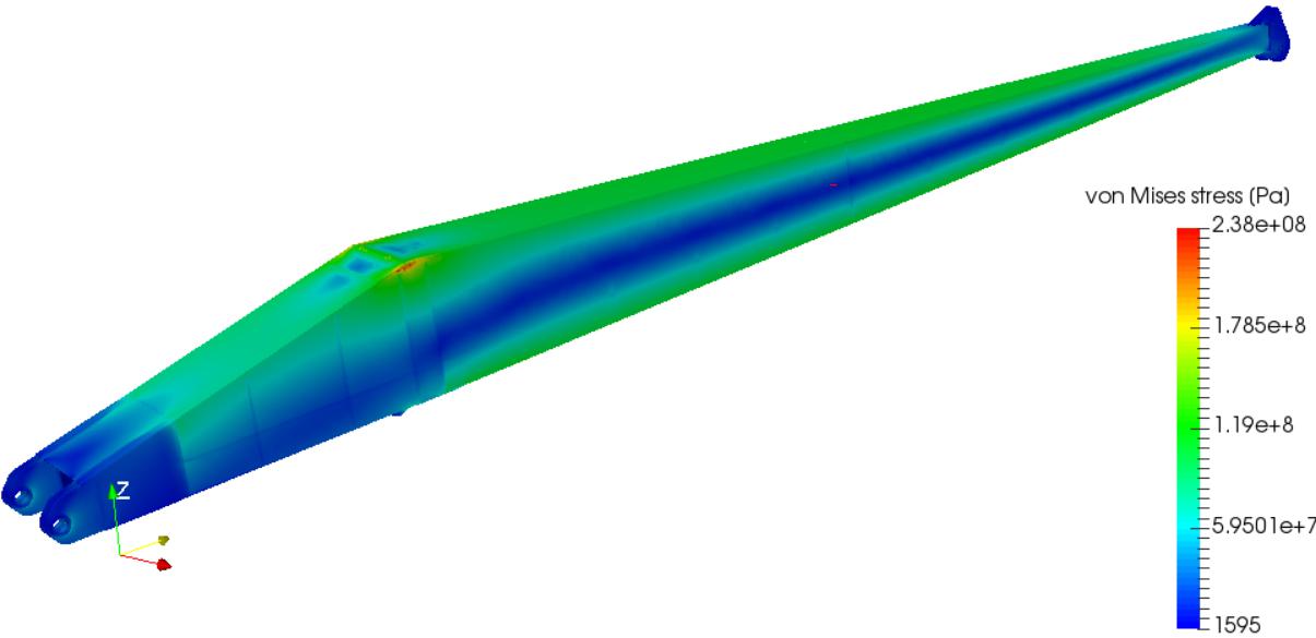
Our assumption was to check how the stresses change during the change of the outreach and on this basis, to optimize the shape of the boom and finally to complete the FEM model, in order to confirm our assumptions. In responsible elements, we use at least two calculation methods, using the FEM program to calculate the element - thanks to this procedure we gain certainty that our assumptions were correct.
The graph stresses in the boom as a function of the distance from the beginning of the boom for its different positions.
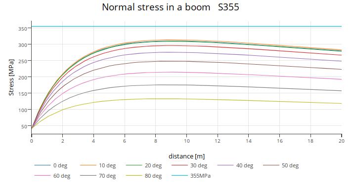
With the help of this calculation algorithm, at the beginning of the design, we can quickly select the optimal shape of the boom, which we will later confirm in the results obtained from the FEM model.
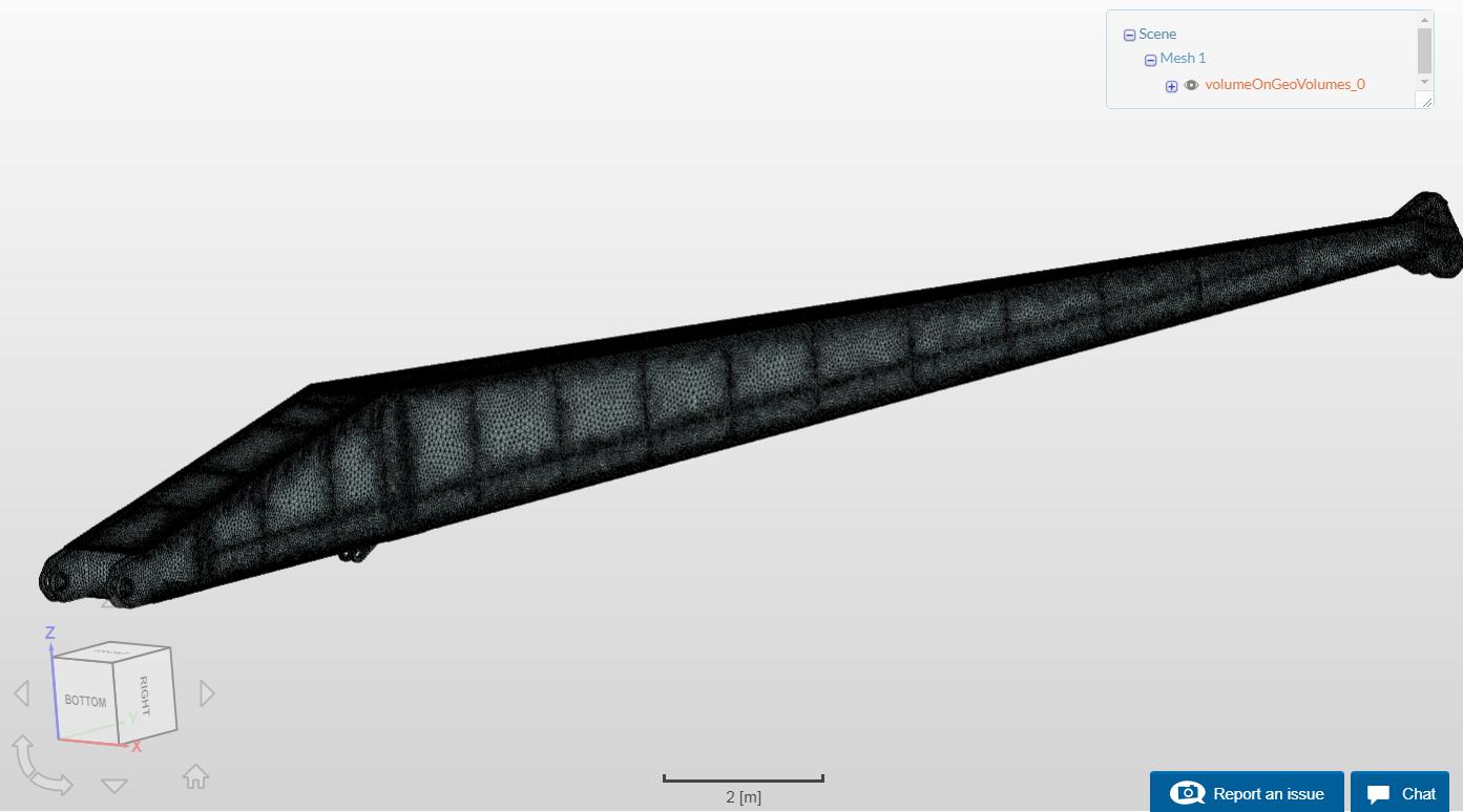
The fully parametric CAD program very easily allows you to modify the boom and quickly prepare the final boom solution for further calculations.
While working on cranes projects, we test FEM programs to quickly convert a CAD model into a FEM model and easily prepare loads to calculate boom in many positions. The works are still ongoing, we develop our models by introducing next variables - such as a variable dynamic coefficient depending on the stiffness of the crane.
Selection of the luffing cylinder
Alike to the boom there is also a variation of the force acting on the cylinder while luffing the boom. Below is an example diagram of the force as a function of the boom inclination. All factors affecting theof force were taken into account, such as, for example, the crane characteristics, wind operation during boom lift (the surface and angle of the wind are changing).
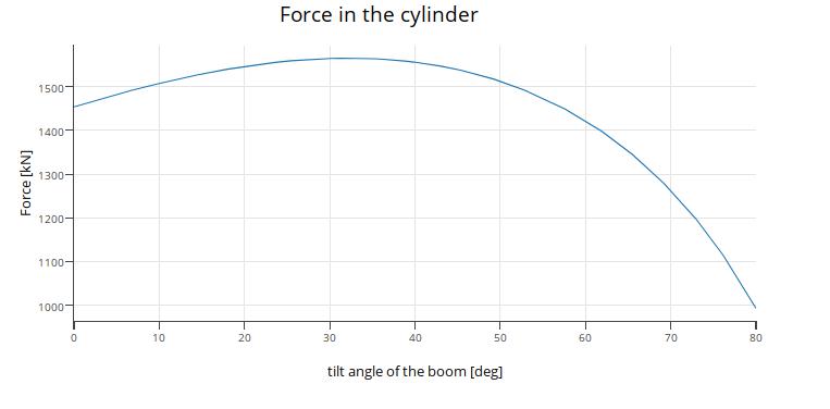
As can seen in this case, the maximum force in the cylinder does not occur in the initial phase of the movement but at an angle of about 35 deg.
In addition, the cylinders are compressed and should be checked for buckling - in accordance with the requirements of the regulations. During stroke of the cylinder, its length is increased and its resistance to buckling is reduced. In addition, having a variable value of force, analysis without exact calculations is much more difficult and badly assumed simplifications may oversize the cylinder, and in the worse case - even choose smaller than required by regulations.
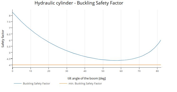
It can be seen in the diagram of the cylinder buckling safety (see the DNV-GL regulations) that the current cylinder meets the requirements of the regulations and the smallest coefficient is approx. 4.5 at a boom inclination angle of 55 deg.
To summarize, the presented results show that it is difficult for cranes to determine in a certain way which position will strain the crane the most. It is necessary to analyze many positions of crane work and without preparing simple tools - it will be very time-consuming and assuming of some simplifications may be burdened with a big mistake. Changing some environmental data or crane characteristics may completely change the load and previously assumed assumptions may turn out to be wrong.